Page updated:
May 22, 2021
Author: Curtis Mobley
View PDF
The Level Sea Surface
The previous chapter on Radiative Transfer Theory developed the equations that govern light propagation within a water body. This chapter now develops the equations that describe how light is reflected and transmitted by the surfaces that bound the water body. These surfaces include the wind-blown sea surface and, in shallow water, an opaque sea floor of sediment or vegetation. There may also be objects within the water column that reflect light.
The Level 1 discussion begins with the basics of reflection and transmission of unpolarized light by a level or flat water surface. Although the ocean is rarely glassy smooth, reflection and transmission by rough, wind-blown surfaces are modeled using the equations for a flat surface applied to each small patch of sea surface, which although tilted from the normal to the mean sea surface can be assumed to be locally flat. Other Level 1 material introduces the bidirectional reflectance distribution function or BRDF. The BRDF is the fundamental quantity for specifying how an opaque surface reflects light.
The first page of the Level 2 material considers reflection and transmission for polarized light. The remainder of the chapter then shows in detail how wind-blown sea surfaces can be described in terms of wave energy spectra and, conversely, how random sea surfaces can be generated starting with wave energy spectra. It can be argued that this material belongs in a text on physical oceanography, which is true. However, these techniques are widely used both for generation of sea surfaces for quantitative modeling of reflection and transmission of light, and for computer animation of sea surfaces as used in many movies. Moreover, you will search in vain for a text anywhere that presents this material at the level of detail given here. It is thus appropriate to include this material in a book on optical oceanography.
Geometric Relations
The wavelength of visible light is much, much less than the millimeter and larger spatial wavelengths of the waves on wind-blown surfaces. Therefore, the laws of geometrical optics and the idealization of a narrow ray of collimated light give a good description of the relevant physical processes.
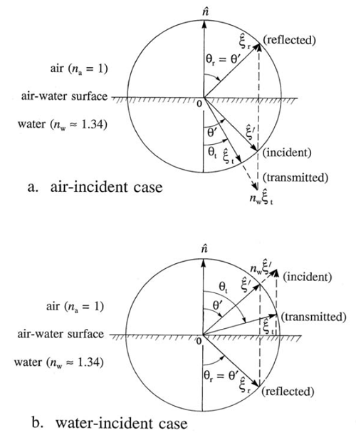
Figure 1 illustrates a level surface with light incident onto the surface from the air side (panel a), and from the water side (panel b). The real index of refraction of the air is , which is taken to be one. is the real index of refraction of the water, which is approximately 1.34 at visible wavelengths. is a unit vector normal to the surface. is a unit vector in the incident direction; and are respectively the directions of the reflected and transmitted rays. is the acute angle between the incident direction and the normal, and and are the angles of the reflected and transmitted rays relative to the normal.
![]()
The incident, reflected, and refracted directions all lie in the plane defined by and . The reflected angle is always equal to the incident angle: , which is known as the Law of Reflection. The incident and transmitted angles are related by
| (1) |
where subscripts 1 and 2 refer to any two media. This equation is usually called Snell’s law, although more properly it should be Snel’s law. It was rediscovered in the west by Willebrord Snel van Royen (1580-1626). In the days when European scientists published in Latin, Snel’s name was Latinized to Snellius, which became Snell as Latin was replaced by German and then English as the common language of physical science. However, this law (in a different but equivalent form) can be traced back to the treatise On Burning Mirrors and Lenses published by the Persian Abu ibn Sahl in Bagdad in 984.
Figure 2 gives a visual representation of the relations between the various unit vectors, angles, and indices of refraction.
For air-incident light, and Snel’s law reads . Then the angle of transmission is given by
| (2) |
The relations between the unit vectors are given by the following equations (with ):
and
where
For the water-incident case, Snel’s law reads , in which case the angle of transmission is given by
| (3) |
The relations between the unit vectors are then
and
where
If , Eq. (3) gives a real value for and light is transmitted from the water to the air. However, if is greater than the critical angle for total internal reflection
| (4) |
then there is no real solution for the inverse sine. In this case, all light incident onto the water side of the air-water surface is reflected back into the water. This is called total internal reflection. The dotted line in the right panel of Fig. 1 represents the critical angle. The red unit vectors illustrate the case with both reflected and transmitted light, and the yellow vectors represent the case of and total internal reflection.
It should be noted that air-incident light with a grazing incident angle of is transmitted into the water at the critial angle: . Thus light from the entire sky is transmitted through the surface into a cone of half angle , which is known as Snel’s cone.
Fresnel’s Equations for Unpolarized Light
The equations of the previous section show the relations between the angles and directions of the incident and the reflected and transmitted light. However, they do not show how much light is reflected or transmitted. That information is given by Fresnel’s equations.
Consider a collimated beam of unpolarized incident light, which has some irradiance measured on a surface normal to the direction of propagation. The fraction of this incident irradiance that is reflected by the air-water surface is
| (5) |
which holds for . For normally incident light, , the reflectance is
| (6) |
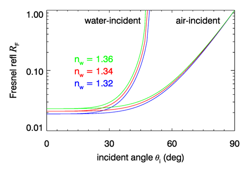
Equations (5) and (6) hold for both air- and water-incident light. Given the incident angle , the transmitted angle is computed using either Eq. (2) or (3), and then Eq. (5) (or 6) can be evaluated. For water-incident light and , . Figure 3 shows the Fresnel reflectance for the range of water indices of refraction at visible wavelengths.
To be completely general, the Fresnel equations should use the complex index of refraction , where is the real index of refraction seen above and is the complex part ( is the absorption coefficient). Thus Eq. (6) should be
However, for water at near-UV to near-IR wavelengths, and the difference is negligible. However can be of order 0.1 to 1 at some UV and far-IR wavelengths, in which case the complex index of refraction must be used.
Conservation of energy requires that the sum of the reflected and transmitted energy equal the incident energy. Thus the fraction of the incident energy that is transmitted is . It can be confusing to see that energy is conserved when different quantities such as plane irradiance, scalar irradiance, or radiance are used to describe the light, or when the incident light is not a single collimated beam. This is discussed in detail on the page on Energy Conservation.
Reflection and transmission are much more complicated when the incident light is polarized. The Fresnel reflectance and transmittance equations for polarized light are given in the Level 2 page on the Fresnel Equations for Polarization of this chapter.
The Law for Radiance
Snel’s law yields an important result governing how unpolarized radiance changes when going from one medium to another, e.g., when crossing an air-water surface. Figure 4 shows two beams of radiance, one incident onto an interface and one transmitted. Let be the incident radiance in medium 1 defined by power passing through an area normal to the direction of photon travel and contained in a solid angle , where is polar angle measured relative to the normal to the surface and is the width of the solid angle in the azimuthal direction. Likewise, is the transmitted radiance in medium 2 defined by the corresponding quantities as illustrated. The azimuthal angle does not change when crossing the surface, so . The incident and transmitted power passes through a common area at the interface.
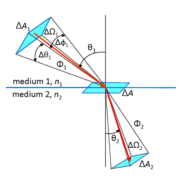
The indices of refraction and are fixed, but the polar angle changes when crossing the interface. Squaring Eq. (1) and differentiating gives
Multiplying each side of this equation by the common value of and rewriting in terms of solid angles gives
which is known as Straubel’s invariant.
The radiances are defined by
Fresnel’s equation gives the transmitted power as . The areas are related by and . Thus the ratios of the incident and transmitted radiances can be written as
or
This result is called the n-squared law for radiance. The quantity is sometimes called the reduced radiance or the basic radiance.
Although energy is conserved when crossing a boundary, the radiance changes by a factor proportional to the change in the index of refraction squared. This is a simple consequence of the change in solid angle resulting from the change in when crossing the boundary. Note that for normal incidence and , and the radiance just below a water surface is times the radiance in the air. Conversely, when going from water to air, the in-water radiance is reduced by a factor of 1.76.
To the extent that losses to absorption and scattering out of the beam can be ignored (sometimes a good approximation for atmospheric transmission, but almost never the case in water), the radiance divided by the square of the index of refraction is constant along any path. This result has even been called the Fundamental Theorem of Radiometry, which is perhaps a bit grandiose given that real beams always lose at least some radiance due to absorption and can lose or gain radiance due to scattering.
Finally, note that the law applies only to radiance transmission. When tracing rays in a Monte Carlo simulation, from which the radiance can be estimated by appropriate binning of the transmitted rays, no factor is applied to the energy of the transmitted rays or to the radiance estimated from the detected rays. This is because the effect is automatically built into the radiance estimate ray by ray as the directions of the individual rays are computed by Snel’s law.
 See comments posted for this page and leave your own.