Page updated:
May 24, 2021
Author: Curtis Mobley
View PDF
The BRDF
This page considers how light is reflected by opaque surfaces, such as a sandy sea bottom. Scientists in many different fields including astronomy, geology, agronomy, the paint industry, camouflage technology, and remote sensing have studied how surfaces reflect light. Unfortunately, different fields often use different measures of “reflectance,” and they all have their own terminology and notation even when they are measuring the same physical quantity. (Recall the Measures of Reflectance page.) There are many opportunities for losing factors of and cosines of angles, and it is sometimes nearly impossible to figure out exactly what is being discussed when reading a paper. This page gives an overview of the definitions, terminology, and notation as needed for optical oceanography and remote sensing.
For the most part, the definitions and terminology used here are given in Hapke (1993), which is a good introductory textbook on reflectance, and in Nicodemus et al. (1977) (referenced here as NBS160). NBS160 is a National Bureau of Standards document that discusses the measurement of reflectance in great detail and is the authoritative document on the subject. (The NBS is now NIST, the National Institute of Standards and Technology. However, we have changed some notation to correspond to what is commonly used in optical oceanography. Table 1 at the end of this page compares the notation used in these books.
For convenience, let the “surface” reflecting the light be a horizontal plane. This can be a physical surface such as a sandy ocean bottom, or it can be simply a particular depth in the water column, say at 1 m above a sea grass bed or at 100 m in optically deep mid-ocean water. To conform to NBS160, we’ll use subscript i to denote incident and r to denote reflected. In the oceanographic setting of a horizontal bottom, the light incident onto the surface is traveling downward, and the light reflected by the surface is traveling upward. Thus we sometimes use subscript d for downward (incident) and u for upward (reflected) when necessary to conform to common oceanographic usage.
In nature, light is usually incident onto a surface from all directions, and some of the incident light gets reflected by the surface into all directions. Therefore, to completely understand the optical properties of a surface, it is necessary to know how the surface reflects light incident from any incident direction into any reflected direction.
Figure 1 shows the geometry used to describe reflectance from a surface. A cartesian (x,y,z) coordinate system is chosen with the surface lying in the x-y plane and with the z axis normal to the surface (upward in our case), an element of which is shown in aqua. There is a collimated light source, which provides the incident light coming from direction ; and there is a detector, which receives the reflected light traveling toward the viewing direction . Surface optical properties usually depend on the wavelength , so the complete description of the reflectance properties of a surface will be a function (the BRDF) of five variables: , and . To make our equations as simple as possible, we drop the , but keep in mind that everything discussed below depends on wavelength.
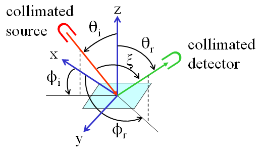
For oceanography, it is often reasonable to assume that the surface is azimuthally isotropic, which means that its reflectance properties depend on the difference of and . (This would not the case for long parallel ripples on a sandy bottom, for example.) The specular direction is the direction that a level mirror surface would reflect light: . The retroreflection direction is the direction of exact backscatter: . The angle between the source and detector is called the phase angle; it is computed from
| (1) |
[Comment: If the source is the sun and the surface is the moon and the earth is the detector, then the phase angle determines the phase of the moon as seen from the earth. This is the historical origin of the term “phase function” for the function that describes the angular pattern of scattered light. The scattering angle as used in radiative transfer theory is the complement of the phase angle: .]
Great care and precise language must be used when talking about reflectance. In particular, “reflectance” always should be preceded by two adjectives: the first describes the source and the second the detector. Thus we have
- The directional-hemispherical reflectance
- tells how much light is reflected from a particular downward direction into the hemisphere of all upward directions
- The hemispherical-directional reflectance
- tells how much light is reflected from all downward directions into a particular upward direction . The remote-sensing reflectance used in optical oceanography is a hemispherical-directional reflectance.
- The bi-hemispherical (i.e., hemispherical-hemispherical) reflectance
- tells how much light is reflected from all downward directions into all upward directions. The irradiance reflectance used in optical oceanography is a bi-hemispherical reflectance.
- The bi-directional (i.e., directional-directional) reflectance
- tells how light is reflected from a particular downward direction into a particular upward direction.
We now define the bi-directional reflectance distribution function (BRDF), which tells us everything we need to know about how a surface reflects light. The following discussion is based on NBS160, which treats these matters in great detail.
Conceptually, we think about a light beam traveling in a particular direction being reflected into another particular direction . But since any source has some finite divergence, and any detector has some finite field of view, we can associate small solid angles and with the incident and reflected beams, respectively. The radiance of the incident beam is , and is the reflected radiance. These quantities are shown in Fig. 2, which is a redrawn version of Fig. 1.
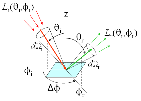
Our goal is to define an inherent optical property that tells us how the reflective properties of the surface vary with incident and reflected directions (and wavelength). Therefore, consider a measurement in which we hold the direction of the detector in Fig. 2 constant while we vary the direction of the source. The BRDF is then defined as
| (2) |
Note that if only the magnitude of the incident radiance changes, the reflected radiance will change proportionately, and the BRDF will remain unchanged. However, if the direction of the incident or reflected beams changes while holding all else constant, the BRDF will in general change.
Equation (2) allows an easy transition to radiative transfer theory. Suppose we want to compute the total radiance heading upward in direction owing to light incident onto the surface from all directions. We then rewrite (2) as
and then integrate over all incident directions to get the total reflected radiance in direction :
This last equation is exactly what is seen (with slightly different notation) in Light and Water (1994) Eq. (4.3), where is called the radiance reflectance function. Clearly,
and the two functions are equivalent ways of describing a surface. In radiative transfer theory irradiances are measured on surfaces normal to the direction of light propagation, whereas actual irradiance measurements are made on the surface of interest. The factor in Eq. (3) just projects the incident beam irradiance onto the horizontal surface. This is one of those places where it is easy to lose a cosine factor when comparing an observational paper and a theory paper. Also, some investigators add a factor of to the numerator of Eq. (2) and define the BRDF as a nondimensional quantity, although this is non-standard. [However, this is how the MODTRAN atmospheric radiative transfer model defines its BRDFs for various types of earth surfaces that form the bottom boundary of the atmosphere.] Finally, note that the BRDF is a reflectance per unit solid angle; it can have any non-negative value. It is only when the BRDF is integrated over solid angle to get, for example, an irradiance reflectance that the resulting irradiance reflectance is bounded by one.
It is emphasized that the BRDF completely describes the net effect of everything that happens on or below the surface where it is measured. For example, if the BRDF is measured in the water column 1 m above a sea grass bed, then all the effects of the light interacting with the grass, sediments, and water below the 1 m level are accounted for in this BRDF. Knowing the BRDF on this imaginary surface would, for example, allow HydroLight to compute the radiance distribution in the region ]above the depth where the BRDF was measured. Predicting or modeling the BRDF of the grass and sediments from first principles is, however, very difficult and requires understanding and modeling all of the extremely complicated interactions of light with the grass and sediment particles.
[Comment: This is how HydroLight models infinitely deep, homogeneous water without actually solving the radiative transfer equation to extreme depth. The BRDF of an infinitely deep, homogeneous layer of water with known inherent optical properties can be found analytically (as in Light and Water Section 9.5). Thus, when HydroLight simulates infinitely deep water, it first computes the BRDF of the infinitely deep water below the maximum depth of interest, , and it then uses that BRDF at just as though there were an actual physical bottom at depth .]
The equations of this page show the BRDF as used in radiative transfer theory. The use of the BRDF as a probability distribution in Monte Carlo simulations is discussed on the page The BRDF as a PDF.
Finally, there is an important reciprocity theorem about what happens if the positions if the source and detector are interchanged. It states simply that
| (5) |
If you measure or define a BRDF that does not obey Eq. (5), then it is simply wrong.
Table 1 compares the notation used in several texts.
| Quantity | This page | Light and Water | Hapke (1993) | NBS160 |
| radiance | ||||
| irradiance | ||||
| single-scattering albedo | — | |||
| scattering angle | — | |||
| mean cosine of scattering angle | — | |||
| phase angle | — | — | ||
| incident polar angle | ||||
| reflected polar angle | ||||
| incident azimuthal angle | set to 0 | |||
| reflected azimuthal angle | ||||
| solid angle | ||||
| BRDF | BRDF | BRDF | ||
| irradiance reflectance |
 See comments posted for this page and leave your own.